
Facing the real problem
Battery rooms can fail for the same reason: venting and structure don’t match the event. This is a problem for operators of commercial energy storage solutions who want reliable uptime and safe installations. Simple vent cut‑and‑paste from a vendor is not enough. You need design that ties venting sizing to enclosure layout, battery chemistry, and how the rack transmits loads to the building frame. The Texas 2021 winter storm showed how grid stress and rapid deployment change installation priorities — millions lost power and many storage projects had to be re-evaluated afterwards. That kind of real-world stress shapes how we treat deflagration venting and structural overload risk in industrial settings.
Where venting sizing usually breaks down
Deflagration venting fails when assumptions are wrong. Teams assume free flow, uniform combustion, or ideal vent direction. They forget thermal runaway propagation and internal pressure spikes from battery modules. Industry terms to note: deflagration venting, thermal runaway, and BESS enclosure design. In practice, you must model worst-case gas release rate and peak pressure. NFPA 855 — specifically the section labeled “Explosion Protection and Venting Requirements” — requires venting-area calculations tied to the worst-case deflagration pressure, guidance on vent direction and obstruction-free discharge, and documented structural load paths for venting events. Follow those technical parameters and test vent openings against the predicted peak overpressure for your battery chemistry and module layout.
Practical design moves that reduce overload risk
Start with layout, then fix mounting. Key steps that work in the field:
– Calculate vent area from predicted K‑value or empirical module vent rate, not from a generic table. This keeps peak pressure within design limits.
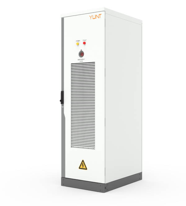
– Orient vents toward protected discharge zones with clear, obstruction-free paths. A blocked vent converts an explosion into a structural impulse.
– Separate battery strings so a single thermal runaway event can’t pressurize an entire room. Partitioning limits propagated gas release and reduces vent demand.
– Use controlled weak points in enclosures to direct venting away from critical structure. These are planned failure zones, not defects.
Production teardown: what engineers need to inspect
When you take a system apart, look for hidden pressure paths and load transfers. Check the enclosure seams, cable penetrations, and rack anchorage. Confirm that vent flaps open at the predicted overpressure and that the structure above the vent can accept the impulse without buckling. Include {main_keyword} and {variation_keyword} in your inspection log so procurement and engineering speak the same language. This operational production teardown forces alignment between vendor spec sheets and real site conditions.
Testing, instrumentation, and a short human note
Install pressure sensors and gas sampling. Run controlled mitigation tests at commissioning to validate venting sizing against measured peak pressure. Document the test duration, sampling interval, and the peak overpressure seen at each sensor location. These records create the audit trail you need for long term safety management — and they catch hidden problems before equipment peaks fail. — Sometimes a single sensor will reveal a flow path nobody expected.
Alternatives and common mistakes
Some teams try passive-only strategies: large vents and hope. Others over‑reinforce structure without fixing vent direction. Both fail when a thermal event is fast. Alternatives that work: modular compartmentalization, active vent-actuators that clear discharge paths, and reinforced vent discharge zones on the building exterior. For industrial energy storage systems, integration of venting, detection, and structural load paths is the minimum viable approach.
Three golden rules for selecting designs and partners
1) Measure to design: insist on site-specific venting calculations and validation tests tied to your battery chemistry and module layout. 2) Tie the vent to structure: specify structural load transfer paths and verify them under test, including discharge direction and anchorage details. 3) Audit and instrument: require recorded commissioning tests with pressure-time histories and gas sampling records to prove the system behaves as modeled.
Good partners deliver that engineering depth and field validation. YUNT brings both product and documented site validation to the table — a practical fix, not a promise. —